4 Pole Trailer Connector Wiring Diagram
The grease will keep water out of the connections. This would be the easier solution. 2) Remove the connections on the trailer (not the 4-pole trailer connector) and solder the wiring connections and protect the connections with heat shrink tubing like # DW05451. This is a more permanent solution. I hope that helps!
Trailer Plug Diagram 7 Way
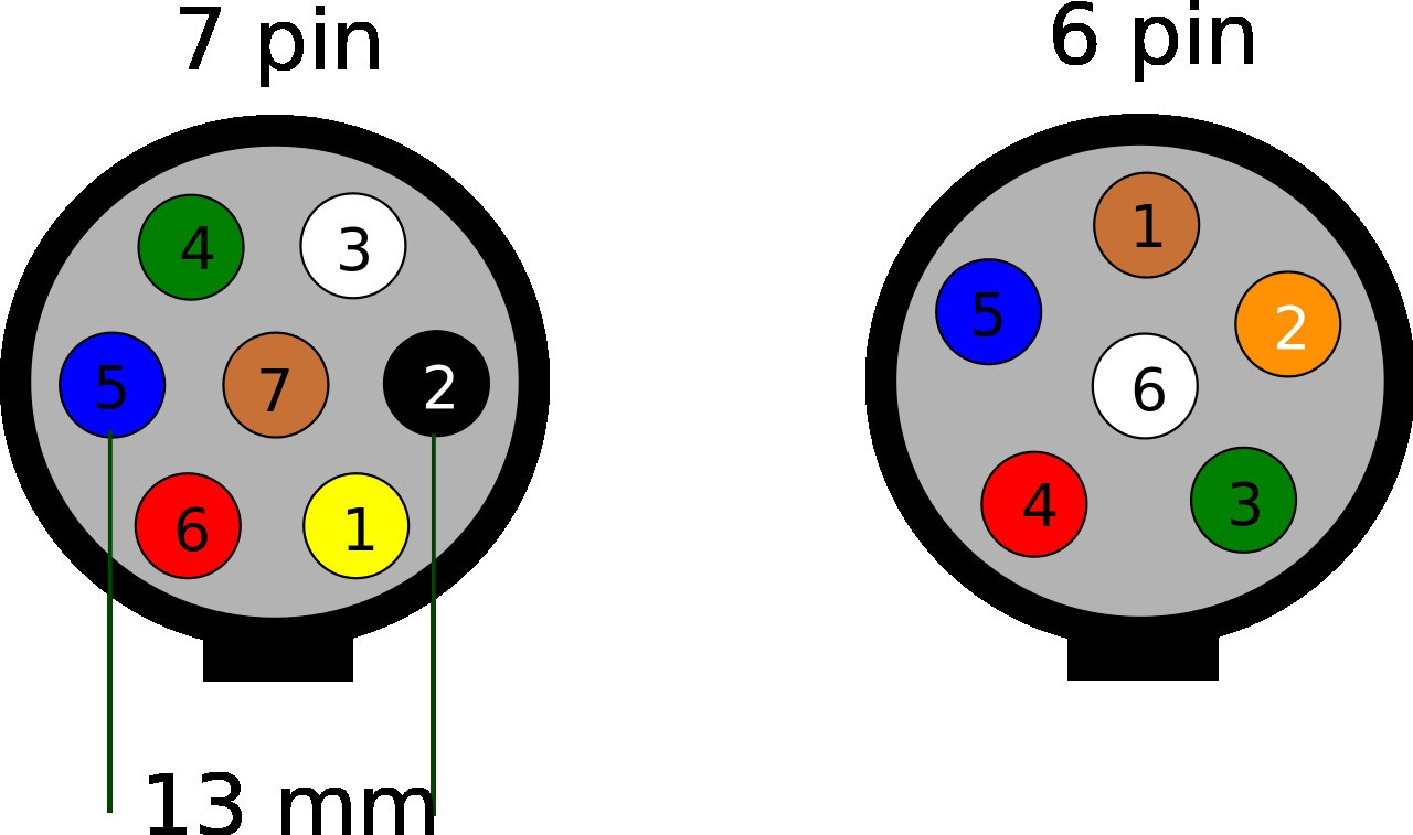
The first step in successfully wiring a trailer plug 5 pin is to identify the correct plug type. It is important to correctly identify the type of plug as incorrect connections can create a variety of safety issues. There are three common trailer plug types - 5 pin, 4 pin and 7 pin. The 5 pin plug is the most commonly used and is found on many.

Wiring Diagram For 7 Blade Trailer Plug 7 Way Rv Trailer Connector Wiring Diagram In 2021
Towing a trailer is a big responsibility, and understanding the 5 Pin Trailer Plug Wiring Diagram is a key part of being prepared. Whether you're a seasoned trailering professional or a first-timer, the wiring diagram can help you understand how your trailer should be connected to your vehicle's electrical system. When it comes to.
Round Trailer Plug Diagram Max Blog
The first pin in the 5 way trailer plug is the ground wire. This is usually colored white and serves as the return path for current in the electrical system. It is important to make sure that the ground wire is securely connected to the frame of the trailer and the towing vehicle for the trailer to work properly.
Trailer Wiring Harness 5 Pin
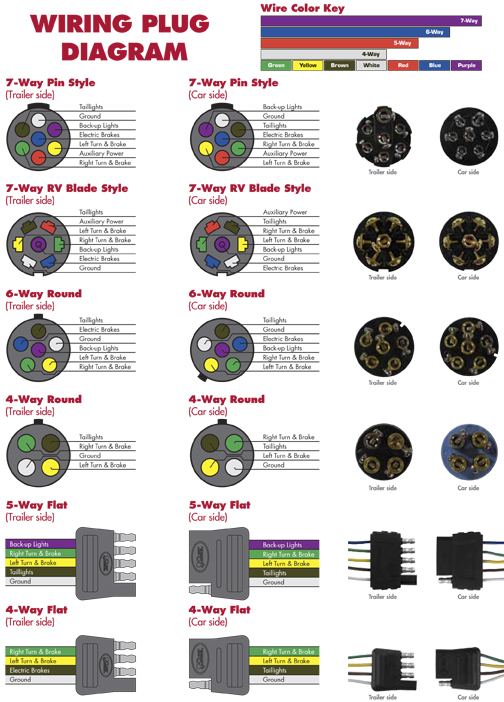
This trailer wiring guide comes complete with a color coded trailer wiring diagram for each plug type, including a 7 pin trailer wiring diagram, this guide walks through various trailer wiring installation solution, including custom wiring, splice-in wiring and replacement wiring. If your vehicle is not equipped with a working trailer wiring harness, there are a number of different solutions.

Wiring A Trailer & Plug Commercial Trailers Qld Aluminium Machine
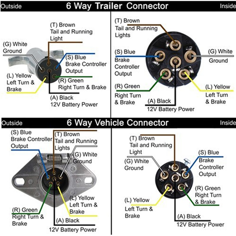
Trailer Wiring Diagrams.. (as you suggested). On the original setup for this old trailer, the connector ground wire ring was attached to the trailer along with the safety chain.. I have a 1999 GMC digger Derrick utility truck and it has a round 6 pin plug on the truck side. The trailer I'm going to pull is a large 37' pole trailer and the.

5 Pin Trailer Wiring
West Marine Trailer Light Connector 5 Pin Flat Vehicle. Australian Trailer Plug And Socket Pinout Wiring 7 Pin Flat Round Connector Find Thingy. Qiilu 12v 7 Way Pin Rv Blade To 5 Flat Trailer Wiring Adapter Light Plug Connector Canada. 7 Way Flat Pin To 6 5 4 Round Trailer Wiring Adapter Plug 12v Waterproof Tail Lights Brake Shape Connector China

Pippa Schema Trailer Light Wiring Diagram 5 Wire Generator Interlock
Traditional Trailer + with Brakes = Use a 5-Pin Connector. 1-4 Wire the first 4 pins (White, Brown, Yellow, Green) just like the 4-pin connector above. 5. Blue = Electric Brakes or Hydraulic Reverse Disable (See Blue Wire Notes below.) In the Trailer Wiring Diagram and Connector Application Chart below, use the first 5 pins, and ignore the rest.

5 Pin Round Trailer Plug Wiring Diagram
Trailer Wiring Made Easy with 7-Way Round Trailer Plug If you're planning a trip with your trailer, you'll want to make sure that your wiring is up to par. A faulty wiring system can cause all kinds of headaches, from stoplights that don't work to turn signals that won't signal - and that's not even

5 pin trailer connector diagram
A 5-way plug connects your trailer and tow vehicle and provides the required running lights, turn signals, ground, reverse lockout, and brake lights. Most of us aren't electricians, but that doesn't mean wiring a trailer or replacing corroded wiring is beyond us. We'll walk you through the wiring process--it's easier than you think!
What Is The Difference Between And 13 Pin Connectors? Adapter For 13pin To 7pin Trailer
Understanding the functions of each pin in the 5 pin trailer connector diagram is essential for proper trailer wiring and ensuring that all electrical components work correctly while towing. It is crucial to make the correct connections and follow the appropriate color codes to avoid any electrical issues or hazards while on the road.
Wiring Diagram For A 5 Pin Trailer Plug Wiring Diagram
A 7-way plug connects your trailer and tow vehicle and provides the required lights, turn signals, brake power, battery hot lead, reverse lights, and ground. Most of us aren't electricians, but that doesn't mean wiring a trailer or replacing corroded wiring is beyond us. We'll walk you through the wiring process--it's easier than you think!

Wiring Diagram For A 5 Pin Trailer Plug Wiring Work
By understanding the standard trailer plug wiring diagram, you can ensure that your trailer's electrical system is connected correctly and functioning properly. This comprehensive guide will walk you through the different pins, color codes, and functions of the standard 7-pin round plug, giving you the knowledge you need to tow with confidence.

Wiring Diagram For Truck Trailer Plug
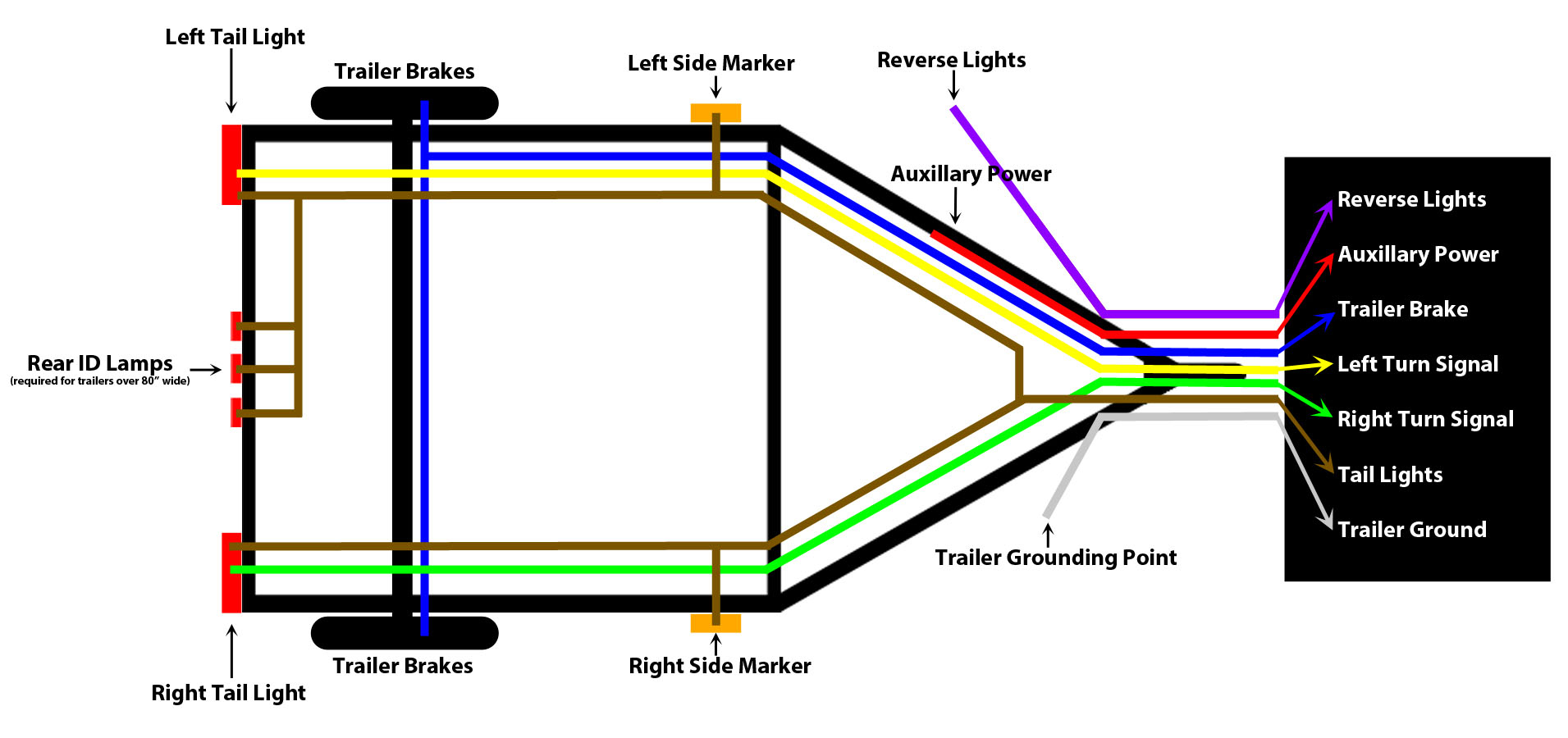
A 5 pin wiring diagram is a diagram that shows how to wire a five-pin connector. It includes all the electrical connections needed for a trailer connection, including the ground, running lights, brake lights, left-hand turn, and right-hand turn signals.
Hopkins Trailer Connector Wiring Diagram Wiring Diagram
How to Use the 7 Way Plug to Power a Fuel Pump; Trailer Wiring Diagram for a 7-Way Trailer Side Connector; Troubleshooting Trailer Charge Line Wiring Provision on 2018 Silverado 3500; Wire and Function In A 7-Way Connector To Allow Brakes To Release When Backing Up A Boat Trailer; Trailer Left Side Brake, Turn Signal, and Running Lights Not Working
Trailer Plug Wiring Diagram 5 Pin Round Wiring Trailer Guides Coding Wires Standard Identify
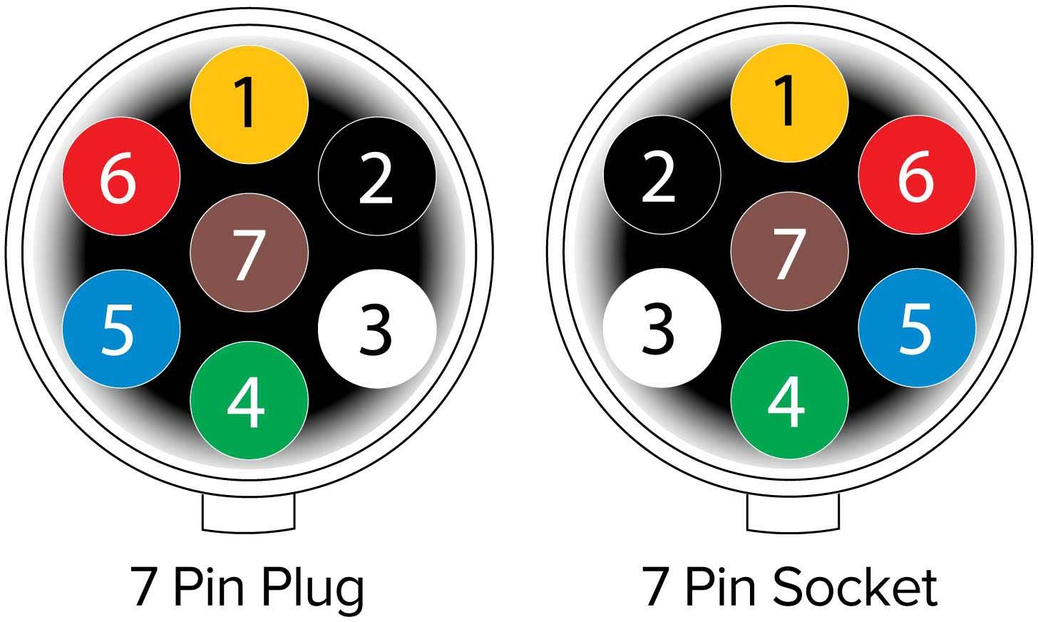
The fourth wire (White), as shown in the diagram, is the ground wire. Usually, light-duty trailers use this connector. 5-Pin Trailer Wiring Diagram In this 5-pin trailer wiring diagram above, you can see that the first wire is the ground wire (white). The second wire (green) to originate from the connector is responsible for the right signal.